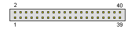
IDE Internal (old) pinout |
hard drive connector |
IDE=Integrated Drive Electronics.Developed by Compaq and Western Digital. Newer version of IDE goes under the name ATA=AT bus Attachment.
Often, the control circuitry is built into the motherboard, eliminating the requirement for a separate Host Adapter. There are 2 types of IDE interfaces...those for the 8-bit XT bus, and those for the 16-bit AT bus .
Note: Direction is Controller relative Devices (Harddisks) | 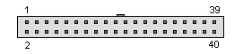 40 pin IDC female connector | |||||||||||||||||||||||||||||||||||||||||||||||||||||||||||||||||||||||||||||||||||||||||||||||||||||||||||||||||||||||||||||||||||||||||||||||||||||||||||||||||||||
Pinouts.ru > Hard drives connectors pinouts listing > Pinout of IDE Internal (old) and layout of 40 pin IDC male connector and 40 pin IDC female connector |
correct | |
| Source(s) of this and additional information: Hardware Book, Dan Williams | 3 reports | |
| Last updated at Sat Jun 25 2005. Submit additions or corrections for this document. | Is this document correct or incorrect? What is your opinion? | |