Hardware pinouts information and cables schemes

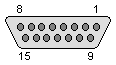
SUN Keyboard/Mouse Connector (old) pinout

connector or cable wiring scheme

bookmark this page

Available on SUN3´s and older


Pin Name Dir Description
1Keyboard In<--Keyboard In
2GND---Ground
3Keyboard Out-->Keyboard Out
4GND---Ground
5Mouse In<--Mouse In
6GND---Ground
7Mouse Out<--Mouse Out (!)
8GND---Ground
9GND---Ground
10VCC-->Power , +5 VDC
11VCC-->Power , +5 VDC
12VCC-->Power , +5 VDC
13VCC-->Power , +5 VDC
14VCC-->Power , +5 VDC
15VCC-->Power , +5 VDC

Note: Direction is Computer relative Keyboard/Mouse.


This information should be correct, but may be not. Please, help us to improve this document!
Is this document CORRECT or INCORRECT? Your opinion will be used to establish document status (showed at the bottom).
Pinouts.ru > Input devices (keyboards, mices, joysticks) pinouts >  Pinout of SUN Keyboard/Mouse Connector (old) and layout of 15 pin D-SUB female connector
Document status: unknown
Source(s) of this and additional information: SUN Field Engineer Handbook, VolumeII, 12/15/93 0 reports
Last updated at Sat Jun 25 2005. Submit additions or corrections for this document. Is this document correct or incorrect? What is your opinion?
[Discuss at the forum] [Back to index] [SUBMIT new pinout]
This page contain parts under Copyright © 2000-2007 by pinouts.ru team.
No any portion of this webpage may be reproduced in any form without visible direct link to this page provided. Webmaster permission required in any other cases.
Efforts have been made to ensure this page is correct, but it is the responsibility of the user to verify the data is correct for their application.
8810 hits since March 4, 2005