APC BackUPS CS/ES smart signalling cable pinout |
connector or cable wiring |
original 940-0128A and analogue of the 940-0128A
If you have a BackUPS CS, you are probably either using it with the USB cable that is supplied or with the 940-0128A supplied by APC, which permits running the UPS in dumb mode. By building your own cable, you can now run the BackUPS CS models (and perhaps also the ES models) using smart signalling and have all the same information that is available as running it in USB mode. The jack in the UPS may be easily use a 8 pin RJ45 connector. It is easy to construct the cable by cutting off one end of a standard RJ45-8 ethernet cable and wiring the other end (three wires) into a standard DB9F female serial port connector.
Though these UPSes are USB UPSes, APC supplies a serial cable (typically with a green DB9 F connector) that has 940-0128A stamped into one side of the plastic serial port connector. Here is suggested scheme of original 940-0128A cable
APC Part# - 940-0128A

     computer      --------- Inside the Connector---------  UPS
     DB9-F         |                                     |  RJ45
     pin - signal  |                                     |  Pin - Color
                   |                                     |
      4     DSR  ->|---+                                 |
                   |   |  diode   resistor               |
      6     DTR  ->|---+---->|----/\/\/\---o kill power  |  8  Orange
                   |                                     |
      1     DCD  <-|----+                                |
                   |    |                                |
      2     RxD  <-|----+----------------+--o low battery|  3  Brown
                   |                     |               |
      7     RTS  ->|----------+--/\/\/\--+               |
                   |          |                          |
                   |          +--/\/\/\--+               |
                   |                     |               |
      8     RI   <-|----+----------------+--o on battery |  2  Black
                   |    |                                |
      9     CTS  <-|----+                                |
                   |                         signal      |
      5     GND  --|-----------------------o ground      |  7  Red
                   |                                     |
      3     TxD    |                                     |
                   |                         chassis     |
      Chassis/GND  |-----------------------o ground      |  4  Black
                   |                                     |
                   |          Not connected              |  1, 5, 6, 9, 10
                   --------------------------------------
| 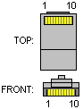 10 pin RJ50 (10P10C) male connector | ||||||||||||||||||||||
Pinouts.ru > GPS, UPS, Switches and other devices cables and adapters schematics > Pinout of APC BackUPS CS/ES smart signalling cable and layout of 9 pin D-SUB female connector and 10 pin RJ50 (10P10C) male connector |
unknown | |
| Source(s) of this and additional information: www.apcupsd.com | 0 reports | |
| Last updated at Thu Jan 10 2008. Submit additions or corrections for this document. | Is this document correct or incorrect? What is your opinion? | |
